
Practice Free HPE6-A85 Exam Online Questions
What does the status of "ALFOE" mean when checking LACP with "show lacp interfaces’"?
- A . The interface on the local switch is configured as static-LAG
- B . LACP is not configured on the peer side
- C . LACP is in a synchronizing process
- D . LACP is working fine with no problems
What is the ideal Aruba access switch for a cost-effective connection to 200-380 clients, printers and APs per distribution rack?
- A . Aruba CX 6400
- B . Aruba CX 6200
- C . Aruba CX 6300
- D . Aruba CX 6000
C
Explanation:
The ideal Aruba access switch for a cost-effective connection to 200-380 clients, printers and APs per distribution rack is the Aruba CX 6200. This switch series is a cloud-manageable, stackable access switch series that is ideal for enterprise branch offices and campus networks, as well as SMBs.
The CX 6200 series offers the following benefits:
– Enterprise-class connectivity: The CX 6200 series supports ACLs, robust QoS, and common protocols such as static and Access OSPF routing.
– Power and speed for users and IoT: The CX 6200 series provides built-in 1/10GbE uplinks and 30W to 60W of Class 4 to Class 6 PoE for powering devices such as APs and cameras.
– Scalable growth made simple: The CX 6200 series supports Aruba Virtual Switching Framework (VSF) that allows you to quickly grow your network to eight members in a single stack using high-performance built-in 10G SFP ports.
– Management flexibility: The CX 6200 series supports a choice of management, including cloud-based and on-prem Central, CLI, switch Web GUI and programmability with AOS-CX operating system, and REST APIs.
The other options are not ideal because:
– Aruba CX 6400: This switch series is a high-availability modular switch series that is ideal for versatile edge access to data center deployments. It offers more performance, scalability, and modularity than the CX 6200 series, but it is also more expensive and complex to deploy and manage. It may not be cost-effective for connecting 200-380 clients per distribution rack.
– Aruba CX 6300: This switch series is a layer 3 stackable access and aggregation switch series that offers Smart Rate and High Power PoE. It offers more features and performance than the CX 6200 series, but it is also more expensive and may not be necessary for connecting 200-380 clients per distribution rack.
– Aruba CX 6000: This switch series is a layer 2 access switch series that offers PoE. It offers less features and performance than the CX 6200 series, and it does not support VSF stacking or routing protocols. It may not be sufficient for connecting 200-380 clients per distribution rack.
References:
https://www.arubanetworks.com/products/switches/access/
https://www.arubanetworks.com/products/switches/access/6200-series/
https://www.arubanetworks.com/products/switches/access/6400-series/
https://www.arubanetworks.com/products/switches/access/6300-series/
https://www.arubanetworks.com/products/switches/access/6000-series/
Based on the "snow ip route" output on an AruDaCX 8400. what type of route is "10.1 20 0/24, vrf default via 10.1.12.2. [1/0]"?
- A . local
- B . static
- C . OSPF
- D . connected
B
Explanation:
A static route is a route that is manually configured on a router or switch and does not change unless it is modified by an administrator. Static routes are used to specify how traffic should reach specific destinations that are not directly connected to the device or that are not reachable by dynamic routing protocols. In Aruba CX switches, static routes can be configured using the ip route command in global configuration mode. Based on the “show ip route” output on an Aruba CX 8400 switch, the route “10.1 20 0/24, vrf default via 10.1.12.2, [1/0]” is a static route because it has an administrative distance of 1 and a metric of 0, which are typical values for static routes.
References:
https://en.wikipedia.org/wiki/Static_routing
https://www.arubanetworks.com/techdocs/AOS-CX_10_04/NOSCG/Content/cx-noscg/ip-routing/static-routes.h
Review the configuration below.
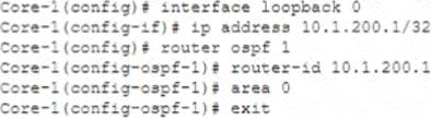
Why would you configure OSPF to use the IP address 10.1.200.1 as the router ID?
- A . The IP address associated with the loopback interface is non-routable and prevents loops
- B . The loopback interface state is dependent on the management interface state and reduces routing updates.
- C . The IP address associated with the loopback interface is routable and prevents loops
- D . The loopback interface state Is independent of any physical interface and reduces routing updates.
D
Explanation:
The reason why you would configure OSPF Open Shortest Path First (OSPF) is a link-state routing protocol that dynamically calculates the best routes for data transmission within an IP network. OSPF uses a hierarchical structure that divides a network into areas and assigns each router an identifier called router ID (RID). OSPF uses hello packets to discover neighbors and exchange routing information. OSPF uses Dijkstra’s algorithm to compute the shortest path tree (SPT) based on link costs and build a routing table based on SPT. OSPF supports multiple equal-cost paths, load balancing, authentication, and various network types such as broadcast, point-to-point, point-to-multipoint, non-broadcast multi-access (NBMA), etc. OSPF is defined in RFC 2328 for IPv4 and RFC 5340 for IPv6. to use the IP address IP address Internet Protocol (IP) address is a numerical label assigned to each device connected to a computer network that uses the Internet Protocol for communication. An IP address serves two main functions: host or network interface identification and location addressing. There are two versions of IP addresses: IPv4 and IPv6. IPv4 addresses are 32 bits long and written in dotted-decimal notation, such as 192.168.1.1. IPv6 addresses are 128 bits long and written in hexadecimal notation, such as 2001:db8::1. IP addresses can be either static (fixed) or dynamic (assigned by a DHCP server). 10.1.200.1 as the router ID Router ID (RID) Router ID (RID) is a unique identifier assigned to each router in a routing domain or protocol. RIDs are used by routing protocols such as OSPF, IS-IS, EIGRP, BGP, etc., to identify neighbors, exchange routing information, elect designated routers (DRs), etc. RIDs are usually derived from one of the IP addresses configured on the router’s interfaces or loopbacks, or manually specified by network administrators. RIDs must be unique within a routing domain or protocol instance. is that the loopback interface state Loopback interface Loopback interface is a virtual interface on a router that does not correspond to any physical port or connection. Loopback interfaces are used for various purposes such as testing network connectivity, providing stable router IDs for routing protocols, providing management access to routers, etc. Loopback interfaces have some advantages over physical interfaces such as being always up unless administratively shut down, being independent of any hardware failures or link failures, being able to assign any IP address regardless of subnetting constraints, etc. Loopback interfaces are usually numbered from zero (e.g., loopback0) upwards on routers. Loopback interfaces can also be created on PCs or servers for testing or configuration purposes using special IP addresses reserved for loopback testing (e.g., 127.x.x.x for IPv4 or ::1 for IPv6). Loopback interfaces are also known as virtual interfaces or dummy interfaces. Loopback interface state Loopback interface state refers to whether a loopback interface is up or down on a router. A loopback interface state can be either administratively controlled (by using commands such as no shutdown or shutdown) or automatically determined by routing protocols (by using commands such as passive-interface or ip ospf network point-to-point ). A loopback interface state affects how routing protocols use the IP address assigned to the loopback interface for neighbor discovery, router ID selection, route advertisement, etc. A loopback interface state can also affect how other devices can access or ping the loopback interface. A loopback interface state can be checked by using commands such as show ip interfacebrief or show ip ospf neighbor. is independent of any physical interface and reduces routing updates.
The loopback interface state is independent of any physical interface because it does not depend on any hardware or link status. This means that the loopback interface state will always be up unless it is manually shut down by an administrator. This also means that the loopback interface state will not change due to any physical failures or link failures that may affect other interfaces on the router.
The loopback interface state reduces routing updates because it provides a stable router ID for OSPF that does not change due to any physical failures or link failures that may affect other interfaces on the router. This means that OSPF will not have to re-elect DRs Designated Routers (DRs) Designated Routers (DRs) are routers that are elected by OSPF routers in a broadcast or non-broadcast multi-access (NBMA) network to act as leaders and coordinators of OSPF operations in that network. DRs are responsible for generating link-state advertisements (LSAs) for the entire network segment, maintaining adjacencies with all other routers in the segment, and exchanging routing information with other DRs in different segments through backup designated routers (BDRs). DRs are elected based on their router priority values and router IDs. The highest priority router becomes the DR and the second highest priority router becomes the BDR. If there is a tie in priority values, then the highest router ID wins. DRs can be manually configured by setting the router priority value to 0 (which means ineligible) or 255 (which means always eligible) on specific interfaces. DRs can also be influenced by using commands such as ip ospf priority, ip ospf dr-delay, ip ospf network point-to-multipoint, etc. DRs can be verified by using commands such as show ip ospf neighbor, show ip ospf interface, show ip ospf database, etc ., recalculate SPT Shortest Path Tree (SPT) Shortest Path Tree (SPT) is a data structure that represents the shortest paths from a source node to all other nodes in a graph or network. SPT is used by link-state routing protocols such as OSPF and IS-IS to compute optimal routes based on link costs. SPT is built using Dijkstra’s algorithm, which starts from the source node and iteratively adds nodes with the lowest cost paths to the tree until all nodes are included. SPT can be represented by a set of pointers from each node to its parent node in the tree, or by a set of next-hop addresses from each node to its destination node in the network. SPT can be updated by adding or removing nodes or links, or by changing link costs. SPT can be verified by using commands such as show ip route, show ip ospf database, show clns route, show clns database, etc ., or send LSAs Link-State Advertisements (LSAs) Link-State Advertisements (LSAs) are packets that contain information about the state and cost of links in a network segment. LSAs are generated and flooded by link-state routing protocols such as OSPF and IS-IS to exchange routing information with other routers in the same area or level. LSAs are used to build link-state databases (LSDBs) on each router, which store the complete topology of the network segment. LSAs are also used to compute shortest path trees (SPTs) on each router, which determine the optimal routes to all destinations in the network. LSAs have different types depending on their origin and scope, such as router LSAs, network LSAs, summary LSAs, external LSAs, etc. LSAs have different formats depending ontheir type and protocol version, but they usually contain fields such as LSA header, LSA type, LSA length, LSA age, LSA sequence number, LSA checksum, LSA body, etc. LSAs can be verified by using commands such as show ip ospf database, show clns database, debug ip ospf hello, debug clns hello, etc. due to changes in router IDs.
The other options are not reasons because:
– The IP address associated with the loopback interface is non-routable and prevents loops: This option is false because the IP address associated with the loopback interface is routable and does not prevent loops. The IP address associated with the loopback interface can be any valid IP address that belongs to an existing subnet or a new subnet created specifically for loopbacks. The IP address associated with the loopback interface does not prevent loops because loops are caused by misconfigurations or failures in routing protocols or devices, not by IP addresses.
– The loopback interface state is dependent on the management interface state and reduces routing updates: This option is false because the loopback interface state is independent of any physical interface state, including the management interface state Management interface Management interface is an interface on a device that provides access to management functions such as configuration, monitoring, troubleshooting, etc. Management interfaces can be physical ports such as console ports, Ethernet ports, USB ports, etc., or virtual ports such as Telnet sessions, SSH sessions, web sessions, etc. Management interfaces can use different protocols such as CLI Command-Line Interface (CLI) Command-Line Interface (CLI) is an interactive text-based user interface that allows users to communicate with devices using commands typed on a keyboard. CLI is one of the methods for accessing management functions on devices such as routers, switches, firewalls, servers, etc. CLI can use different protocols such as console port serial communication protocol Serial communication protocol Serial communication protocol is a method of transmitting data between devices using serial ports and cables. Serial communication protocol uses binary signals that represent bits (0s and 1s) and sends them one after another over a single wire. Serial communication protocol has advantages such as simplicity, low cost, long
When using the OSPF dynamic routing protocol on an Aruba CX switch, what must match on the neighboring devices to exchange routes?
- A . Hello timers
- B . DR configuration
- C . ECMP method
- D . BDR configuration
A
Explanation:
OSPF Open Shortest Path First. OSPF is a link-state routing protocol that uses a hierarchical structure to create a routing topology for IP networks. OSPF routers exchange routing information with their neighbors using Hello packets, which are sent periodically on each interface. To establish an adjacency Adjacency is a relationship formed between selected neighboring routers for the purpose of exchanging routing information.,
OSPF routers must agree on several parameters, including Hello timers, which specify how often Hello packets are sent on an interface. If the Hello timers do not match between neighboring routers, they will not form an adjacency and will not exchange routes.
References: https://www.arubanetworks.com/techdocs/ArubaOS_86_Web_Help/Content/arubaos-solutions/osfp/
Which Protocol Data Unit (PDU) represents the network layer PDU?
- A . PDU3 – Packet
- B . PDU4 – Segment
- C . PDU1 – Signal
- D . PDU2 – Frame
A
Explanation:
In the context of the OSI model, the network layer is responsible for packet forwarding including routing through intermediate routers. Hence, the network layer PDU is known as a packet.
An AP signal strength of .0000001 milliwatts equals how many dBm?
- A . -90 dBm
- B . -60 dBm
- C . -70 dBm
- D . -80 dBm
C
Explanation:
An AP signal strength of .0000001 milliwatts is equivalent to -80 dBm. The dBm scale is logarithmic, with every 10 dBm representing a tenfold increase or decrease in power. A signal strength of 1 milliwatt (mW) is 0 dBm, so a signal strength of .0000001 mW is 80 decibels less than 1 mW, which is -80 dBm.
A network technician is using Aruba Central to troubleshoot network issues.
Which dashboard can be used to view and acknowledge issues when beginning the troubleshooting process?
- A . the Alerts and Events dashboard
- B . the Audit Trail dashboard
- C . the Reports dashboard
- D . the Tools dashboard
A
Explanation:
The Alerts and Events dashboard displays all types of alerts and events generated for events pertaining to device provisioning, configuration, and user management. You can use the Config icon to configure alerts and notifications for different alert categories and severities1. You can also view the alerts and events in the List view and Summary view2.
References:
1 https://www.arubanetworks.com/techdocs/central/latest/content/nms/alerts/configuring-alerts.htm
2 https://www.arubanetworks.com/techdocs/central/latest/content/nms/alerts/viewing-alerts.htm
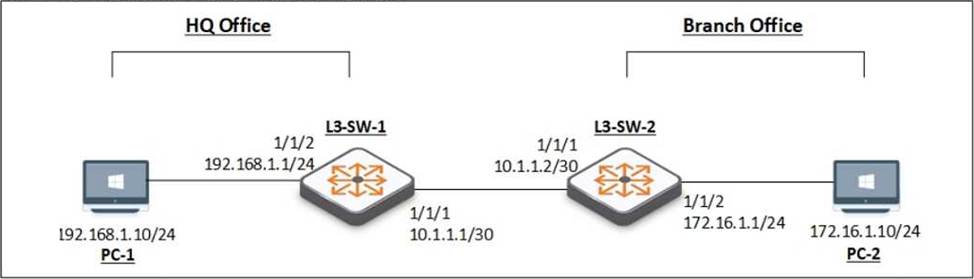
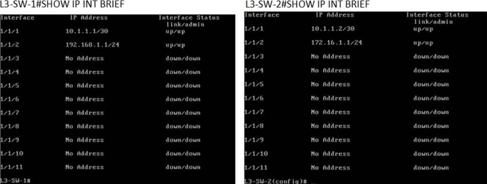
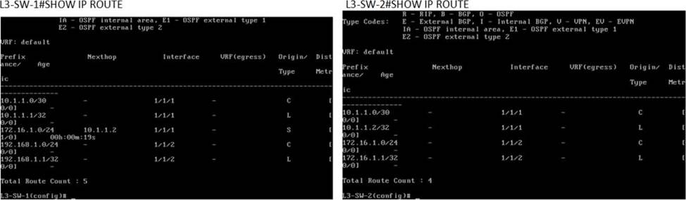
You have been asked to troubleshoot failed connectivity between a local subnet in the HQ Office and a remote subnet in the Branch Office. PC1 is unable to ping PC2.
Use the provided topology and show command output to identify the reason for the failure:
- A . On Branch Office – L3-SW-2- There is no Layer 3 SVI configured in the correct subnet.
- B . On HQ Office L3-SW-1 – There is no route to the Branch Office.
- C . On HQ Office L3-SW-1 – The switch does not have a static default route to the internet.
- D . On Branch Office L3-SW-2- The switch does not have a static route to the HQ Office Local Subnet.
D
Explanation:
Using the provided topology and show command output, it can be determined that L3-SW-2 in the Branch Office does not have a route to reach the subnet where PC1 resides (192.168.1.0/24 in the HQ Office). L3-SW-1 in the HQ Office has a route to the Branch Office subnet (172.16.1.0/24), but without the reciprocal route on L3-SW-2, traffic from the Branch Office will not be able to reach the HQ Office subnet, hence PC1 cannot ping PC2.
Which part of the WPA Key Hierarchy is used to encrypt and/or decrypt data”
- A . Pairwise Temporal Key (PTK)
- B . Pairwise Master Key (PMK)
- C . Key Confirmation Key (KCK)
- D . number used once (nonce)
A
Explanation:
The part of WPA Key Hierarchy that is used to encrypt and/or decrypt data is Pairwise Temporal Key (PTK). PTK is a key that is derived from PMK Pairwise Master Key (PMK) is a key that is derived from PSK Pre-shared Key (PSK) is a key that is shared between two parties before communication begins, ANonce Authenticator Nonce (ANonce) is a random number generated by an authenticator (a device that controls access to network resources, such as an AP), SNonce Supplicant Nonce (SNonce) is a randomnumber generated by supplicant (a device that wants to access network resources, such as an STA), AA Authenticator Address (AA) is MAC address of authenticator, SA Supplicant Address (SA) is MAC address of supplicant using Pseudo-Random Function (PRF).
PTK consists of four subkeys:
– KCK Key Confirmation Key (KCK) is used for message integrity check
– KEK Key Encryption Key (KEK) is used for encryption key distribution
– TK Temporal Key (TK) is used for data encryption
– MIC Message Integrity Code (MIC) key
The subkey that is specifically used for data encryption is TK Temporal Key (TK). TK is also known as Pairwise Transient Key (PTK). TK changes periodically during communication based on time or number of packets transmitted.
The other options are not part of WPA Key Hierarchy because:
– PMK: PMK is not part of WPA Key Hierarchy, but rather an input for deriving PTK.
– KCK: KCK is part of WPA Key Hierarchy, but it is not used for data encryption, but rather for message integrity check.
– Nonce: Nonce is not part of WPA Key Hierarchy, but rather an input for deriving PTK.
References:
https://en.wikipedia.org/wiki/Wi-Fi_Protected_Access#WPA_key_hierarchy_and_management
https://www.cwnp.com/wp-content/uploads/pdf/WPA2.pdf